In a previous article, we have seen how to use RF433 chips with Arduino.
Pros for these chips are they are cheap and easy to use, cons is that they provide little or no tuning.
Hence, lets play a bit now with 2 texas cc1101 : with this component, we can play with the frequency (from 315 to 915), the modulation (ask, fsk, etc) and tons of other parameters.
You can use smartRF (optional) to dive into parameters.
First lets start with the pins of the cc1101.
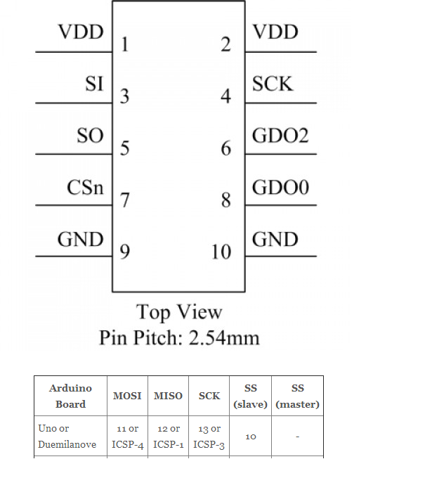
Here how it will connect to the arduino uno board (see here for other boards) :

To use the CC1101, you will need the panstamp library here.
Note that it will also work with the elechouse library here.
The initial thread on the Arduino forum.
Now lets have a look at the sketches.
Sending …
#include "EEPROM.h"
#include "cc1101.h"

CC1101 cc1101;

// The LED is wired to the Arduino Output 4 (physical panStamp pin 19)
#define LEDOUTPUT 7

// counter to get increment in each loop
byte counter;
byte b;
//byte syncWord = 199;
byte syncWord[2] = {199, 0};

void blinker(){
digitalWrite(LEDOUTPUT, HIGH);
delay(100);
digitalWrite(LEDOUTPUT, LOW);
delay(100);
}

void setup()
{
Serial.begin(38400);
Serial.println("start");

// setup the blinker output
pinMode(LEDOUTPUT, OUTPUT);
digitalWrite(LEDOUTPUT, LOW);

// blink once to signal the setup
blinker();

// reset the counter
counter=0;
Serial.println("initializing...");
// initialize the RF Chip
cc1101.init();

//cc1101.setSyncWord(&syncWord, false);
cc1101.setSyncWord(syncWord, false);
cc1101.setCarrierFreq(CFREQ_433);
cc1101.disableAddressCheck();
//cc1101.setTxPowerAmp(PA_LowPower);

delay(1000);

Serial.print("CC1101_PARTNUM "); //cc1101=0
Serial.println(cc1101.readReg(CC1101_PARTNUM, CC1101_STATUS_REGISTER));
Serial.print("CC1101_VERSION "); //cc1101=4
Serial.println(cc1101.readReg(CC1101_VERSION, CC1101_STATUS_REGISTER));
Serial.print("CC1101_MARCSTATE ");
Serial.println(cc1101.readReg(CC1101_MARCSTATE, CC1101_STATUS_REGISTER) & 0x1f);

Serial.println("device initialized");
//Serial.println("done");
}

void send_data() {
CCPACKET data;
data.length=10;
byte blinkCount=counter++;
data.data[0]=5;
data.data[1]=blinkCount;data.data[2]=0;
data.data[3]=1;data.data[4]=0;
//cc1101.flushTxFifo ();
Serial.print("CC1101_MARCSTATE ");
Serial.println(cc1101.readReg(CC1101_MARCSTATE, CC1101_STATUS_REGISTER) & 0x1f);
if(cc1101.sendData(data)){
Serial.print(blinkCount,HEX);
Serial.println(" sent ok :)");
blinker();
}else{
Serial.println("sent failed :(");
blinker();
blinker();
}
}

void loop()
{
send_data();
delay(4000);
}
Receiving …
#include "EEPROM.h"
#include "cc1101.h"

// The LED is wired to the Arduino Output 4 (physical panStamp pin 19)
#define LEDOUTPUT 4

// The connection to the hardware chip CC1101 the RF Chip
CC1101 cc1101;

byte b;
byte i;
byte syncWord = 199;
long counter=0;
byte chan=0;

// a flag that a wireless packet has been received
boolean packetAvailable = false;

void blinker(){
digitalWrite(LEDOUTPUT, HIGH);
delay(100);
digitalWrite(LEDOUTPUT, LOW);
delay(100);
}

/* Handle interrupt from CC1101 (INT0) gdo0 on pin2 */
void cc1101signalsInterrupt(void){
// set the flag that a package is available
packetAvailable = true;
}

void setup()
{
Serial.begin(38400);
Serial.println("start");

// setup the blinker output
pinMode(LEDOUTPUT, OUTPUT);
digitalWrite(LEDOUTPUT, LOW);

// blink once to signal the setup
blinker();
// initialize the RF Chip
cc1101.init();

cc1101.setSyncWord(&syncWord, false);
cc1101.setCarrierFreq(CFREQ_433);
cc1101.disableAddressCheck(); //if not specified, will only display "packet received"
//cc1101.setTxPowerAmp(PA_LowPower);

Serial.print("CC1101_PARTNUM "); //cc1101=0
Serial.println(cc1101.readReg(CC1101_PARTNUM, CC1101_STATUS_REGISTER));
Serial.print("CC1101_VERSION "); //cc1101=4
Serial.println(cc1101.readReg(CC1101_VERSION, CC1101_STATUS_REGISTER));
Serial.print("CC1101_MARCSTATE ");
Serial.println(cc1101.readReg(CC1101_MARCSTATE, CC1101_STATUS_REGISTER) & 0x1f);

attachInterrupt(0, cc1101signalsInterrupt, FALLING);

Serial.println("device initialized");
}

void ReadLQI()
{
byte lqi=0;
byte value=0;
lqi=(cc1101.readReg(CC1101_LQI, CC1101_STATUS_REGISTER));
value = 0x3F - (lqi & 0x3F);
Serial.print("CC1101_LQI ");
Serial.println(value);
}

void ReadRSSI()
{
byte rssi=0;
byte value=0;

rssi=(cc1101.readReg(CC1101_RSSI, CC1101_STATUS_REGISTER));

if (rssi >= 128)
{
value = 255 - rssi;
value /= 2;
value += 74;
}
else
{
value = rssi/2;
value += 74;
}
Serial.print("CC1101_RSSI ");
Serial.println(value);
}

void loop()
{
if(packetAvailable){
Serial.println("packet received");
// Disable wireless reception interrupt
detachInterrupt(0);

ReadRSSI();
ReadLQI();
// clear the flag
packetAvailable = false;

CCPACKET packet;

if(cc1101.receiveData(&packet) > 0){
if(!packet.crc_ok) {
Serial.println("crc not ok");
}

if(packet.length > 0){
Serial.print("packet: len ");
Serial.print(packet.length);
Serial.print(" data: ");
for(int j=0; j<packet.length; j++){
serial.print(packet.data[j],hex);
serial.print(" ");
}
serial.println(".");

 }
}
 // Enable wireless reception interrupt attachInterrupt(0, cc1101signalsInterrupt, FALLING);
}
}
Voila :)
You know should not a bit better on the cc1101 pins, on how to connect it to the arduino and you have basic code to developp your projects.
thanks for your message.
Hi. Thanks for the code, it was very usefull for me to test 2 modules that I just received.
P.S.On Opera the code is messed up a little. The double quote in the Serial.print command aren’t displayed proprely.
hi
i’m using an Arduino Uno with the module
http://www.elechouse.com/elechouse/index.php?main_page=product_info&products_id=802
I’m trying to use the code but I have a problem
setting the frequency to 443 MHz does not compile (works with frequency 868 MHz,no header reference for CFREQ_433 )
I also have error when printing to serial port calling the function readReg.
Using libraries of ElecHouse, transmission works fine but is limited to 40-50 m
thanks
Luca
Hi Luca,
I have attached the panstamp library I use here : http://labalec.fr/erwan/?attachment_id=765 .
The 433 cfreq is defined in cc1101.h.
Let me know if the attached panstamp zip file helps. (or not).
Regards,
Erwan
Yes, this helped out
thanks
Hi,
Good tutorial. I am doing your tutorial on ARDUINO MEGA 2560. I edited the spi.h from panstamp so that pinnings would be correct. The only problem I’m getting is that, the receiver can’t start receiving unless I manually disconnect and reconnect the GDO pin from the arduino interrupt pin. Alternative is to short the GDO and the PIN2(external interrupt) to 3.3V to start receiving.
Regards,
Kit
Thanks for the feedback !
/Erwan
Hi, I am struggling trying to get this running with my mega 2560 R3… would you be able to share your project just so I can get this transmitting?
Thanks,
-Josh
HELLO ,
I CANT SE IN YOUR SCHEMA ANY ANTENA THAT IS NEEDED CAN YOU PLEASE ADVICE ?
Hi,
My cc1101 components has its own antenna soldered on the chip.
See example here : http://s3.electrodragon.com/wp-content/uploads/2011/11/CC1101.jpg .
Regards,
Erwan
Your article is the only thing I found in google with both code and pinout. Works like a charm, THANKS! I used dx.com/p/diy-cc1101-433mhz-wireless-transceiver-module-for-arduino-green-2-pcs-149251
i tried to execute this code but it gives be compiling error that
In file included from C:\Users\aleena\Downloads\arduino-1.0.5-r2-windows\arduino-1.0.5-r2\libraries\panstamp/cc1101.h:48,
from panstamp_TX.ino:2:
C:\Users\aleena\Downloads\arduino-1.0.5-r2-windows\arduino-1.0.5-r2\libraries\panstamp/spi.h:81: error: ‘CC1101’ does not name a type
In file included from C:\Users\aleena\Downloads\arduino-1.0.5-r2-windows\arduino-1.0.5-r2\libraries\panstamp/cc1101.h:50,
from panstamp_TX.ino:2:
C:\Users\aleena\Downloads\arduino-1.0.5-r2-windows\arduino-1.0.5-r2\libraries\panstamp/ccpacket.h:69: error: ‘CC1101’ does not name a type
In file included from panstamp_TX.ino:2:
C:\Users\aleena\Downloads\arduino-1.0.5-r2-windows\arduino-1.0.5-r2\libraries\panstamp/cc1101.h:520: error: expected constructor, destructor, or type conversion before ‘class’
C:\Users\aleena\Downloads\arduino-1.0.5-r2-windows\arduino-1.0.5-r2\libraries\panstamp/cc1101.h:838: error: ‘CC1101’ does not name a type
panstamp_TX.ino: In function ‘void setup()’:
panstamp_TX:37: error: ‘cc1101’ was not declared in this scope
panstamp_TX.ino: In function ‘void send_data()’:
panstamp_TX:66: error: ‘cc1101’ was not declared in this scope »
what does this mean and how can i remove this problem
Hi,
Are you using the panstamp library provided on this blog?
Regards,
Erwan
i am using panstamp libraries with it but it gives me the above error
see previous comment
hi,
my question is that on cc1101 the max voltage that can be on any digital pin is 3.9v but the high or low voltage levels for arduino correspond to +5v and 0v so if we directly connect the pin out as given in your diagram would there be any damage to cc1101
I am using a 3.3 voltage.
Specs from TI mentions 3.9 max.
I would not try a higher voltage unless you are dary and dont care losing 10 € !
@alenna
You must power the CC1101 with 3.3V but its I/O pins are tolerant to 5V, so you can connect them directly ont arduino I/O pins
use an LDO33 for example from the +5 V of the arduino to obtaine a 3.3V, but do not use the 3.3V of the arduino (I have a nano V3) that comes from the USB/UART tranceiver because it have no power…
hey,
i tried the similar connections and same code….. but i get 0 wtever i try 2 read…….. can any1 help wid this???
Hi,
May be there is nothing to read?
Do you have a device sending datas?
Regards,
Erwan
I am using mega and cc1101 with sucess. but im facing the same problem that kit. I have to short GDO0 with 3.3v just once to start receiving. Is the GDO0 set with the correct function?
Maybe you could alter this by setting the registers atfter the init call?
Something like cc1101.writeReg(0x02,0x06); // gdo0 output pin configuration ?
Regards,
Erwan
I see many people are passing by and even posting.
Good 🙂
May be a passing by reader would know how to send and receive ASK/OOK packets?
I need this to send/receive to weather stations on RF433…
Ask ook is not that difficult to operate. to start with, get the settings from smartrf studio. do take note that you need to manually adjust the AGC registers for optimum setting for ask ook – there is an application note for it. I always turn on the manchester whenever i use the ask/ook.
Nice blog by the way.
Hi,
Thx for your feedback.
I finally managed to find the right settings for ASK OOK.
Now need to succeed in communicating with other ASK OOK devices (chacon modules)
Regards,
Erwan
No problem. Good luck to you. I succeeded with communicating with other ask ook non cc1101 device using synchronous mode. But that was cpu intensive. There is a way to use normal packet mode but it is not quite straightforward
Any cc1101 registers setup you can share around ask ook, i’ll take it 🙂
Thanks,
Erwan
The settings is quite straightforward if you will use the synchronous mode. Just use smart rf studio and set the synchronous mode and the necessary settings then you are good to go. But you need to manually decode the packets this way and this is quite cpu intensive than the normal packet mode.
I got it. The problem was that the receiver needs the command « cc1101.setRxState » to start receiving without short the gdo0 pin.
Happy it works out for you.
And also, thanks for sharing !
Hi, congratulations for the code,
I’m having problems with the ReadLQI on the line
“ value = 0x3F – (lqi & 0x3F); ”
The error is :
Receptor_CC1101:70: error: stray ‘\’ in program
Receptor_CC1101:83: error: stray ‘\’ in program
Receptor_CC1101.ino: In function ‘void ReadLQI()’:
Receptor_CC1101:70: error: expected `;’ before ‘u2013’
Receptor_CC1101.ino: In function ‘void ReadRSSI()’:
Receptor_CC1101:83: error: expected `;’ before ‘u2013’
what does this mean and how can i remove this problem
The code was wrongly formatted (due to wordpress formatting).
Copy/paste the code, give it another try and let me know.
Hi Erwan,
I’m working with mega and nrf24l01, but i have a limitation and only can work with 6 channels RF, each channel with 1 RF Module.
I read than CC1101 module, can work in multichannel mode.(i assume ‘N’ channels and ‘N’ RF modules).
that is true?, can I read and write to each channel separately? no matter how many are?
thank’s
Alejandro
Hi Alejandro,
I cannot answer that one.
The way I do is to setup my channel during the setup/config phase, then read/write.
I believe I can probably change the channel between two run but this is probably not what you are looking for.
I would advise to push that question on the TI forum.
Regards,
Erwan
Hi Erwan, thank you for the tutorial.
I am having difficulties trying to get this running using two Arduino Mega 2560’s. I am using the Arduino 1.0.5-r2 IDE to code with and these modules: http://www.ebay.ca/itm/251174999449?ssPageName=STRK:MEWNX:IT&_trksid=p3984.m1497.l2649. I have modded the spi.h file to coincide with the spi of the boards.
When the Send program runs, it gives this output:
start
initializing…
CC1101_PARTNUM 0
CC1101_VERSION 0
CC1101_MARCSTATE 0
device initialized
CC1101_MARCSTATE 0
However, that is all it prints out. It seems as though it is getting caught up in the actual send function in the cc1101.cpp file because it simply does not come out of the if statement either way to tell me that it either failed or succeeded. I am at a total loss and have been quite excited to get this project working. Hopefully you can assist me!
Thank you in advance!
« CC1101_VERSION 0 » is not good.
i can see different root causes :
-your wiring is not good (or pins definition)
-your registers are not set correctly
You should not need to modify spi.h (I believe).
Use this article to find out your pins : http://arduino.cc/en/Reference/SPI .
I use 10,11,12,13 for my SPI pins and Pins 2 for my interrupt (GD0).
Regards,
Erwan
Hi Erwan,
Thank you for getting back to me so quickly. I believe I needed to modify the spi.h file because I am using the arduino mega 2560 and so the MOSI, MISO, SCK, and SS are changed to 51, 50, 52, and 53 respectively. Please correct me if I am wrong! The only changes I made to the spi.h file were literally changing those numbers.
I have soldered jumper wires to the rf board pins to ensure I have a good connection and there are no visible shorts.
So to me the next place to look would be ensuring that I have connected each pin to the the correct arduino pin (which I have done many times and I cannot see any errors) or the registers.
I was under the impression that if I was using the panstamp library and your code, that the registers would be configured properly?
What are the expected values for the version, partnum and marcstate?
Do you have any suggestions for a systemic approach to trouble shooting this problem I am having? or some good references so that I may learn more about this?
Again, thank you in advance!
-Josh
Now that I am looking at your code again, it seems I had changed the line from
cc1101.setSyncWord(&syncWord, false);
to
cc1101.setSyncWord(&syncWord, false);
and the same for the readReg for MARCSTATE line in setup.
I also changed the third one in send_data()
I did this because as I was testing your code it would not compile because it would say « error: ‘amp’ was not declared in this scope and without it, the code compiled. Is it possible this is what has caused my system to not function correctly? what is amp? where is it supposed to be defined and how do I define it?
I am using Arduino 1.0.5-r2
My full error read out is:
sketch_jun09a.ino: In function ‘void setup()’:
sketch_jun09a:39: error: ‘amp’ was not declared in this scope
sketch_jun09a:39: error: expected `;’ before ‘)’ token
sketch_jun09a:51: error: expected `;’ before ‘)’ token
sketch_jun09a.ino: In function ‘void send_data()’:
sketch_jun09a:66: error: ‘amp’ was not declared in this scope
sketch_jun09a:66: error: expected `;’ before ‘)’ token
« & a m p ; » comes from bad html formatting in wordpress : « & » is sometimes displayed » & a m p ; ».
but i have fixed that in wordpress some weeks ago : can you copy paste the code again to be sure?
if you keep getting these errors after that, i will attach my sketch to that article.
/Erwan
Hi Josh,
The SPI files are native arduino librairies : i would expect that they natively support the different arduino’s.
I cannot find these pins definitions you are mentionning in my own spi.h : can you copy paste these line here?
Regards,
Erwan
Hi Erwan,
After obsessing for ~12hrs trying to fix this, I believe I got it working based on these results:
CC1101_PARTNUM 0
CC1101_VERSION 4
CC1101_PKTSTATUS 16
CC1101_MARCSTATE 1
CC1101_TXBYTES 0
device initialized
CC1101_MARCSTATE 1
CC1101_TXBYTES 0
CC1101_TXFIFO 0
0 sent ok 🙂
CC1101_MARCSTATE 13
CC1101_TXBYTES 0
CC1101_TXFIFO 123
1 sent ok 🙂
CC1101_MARCSTATE 13
CC1101_TXBYTES 0
CC1101_TXFIFO 11
2 sent ok 🙂
CC1101_MARCSTATE 13
CC1101_TXBYTES 0
CC1101_TXFIFO 123
3 sent ok 🙂
The I was able to find the pin map for the ATmega 2560, which is used by the Arduino mega 2560, here: http://arduino.cc/en/Hacking/PinMapping2560
(The SPI pins are actually listed on the http://arduino.cc/en/Reference/SPI link you sent me)
From this hurdle I have learnt that both the panstamp and the ELECHOUSE libraries were created with only the ATmega 328p (possibly the older models as well, I did not check to confirm) in mind which is used by the UNO and Duemilanove.
I ended up using the panstamp library however I had to make small modifications to « panstamp.cpp », and « spi.h ». The Arduino mega 2560 does not have a single PRR, rather it has both PRR0 and PRR1. I needed to change PRR–>PRR0 in the « panstamp.cpp » in two locations.
In order to get the SPI/GDO0 working I needed to change the original SPI definitions in « spi.h » to:
/**
* SPI pins
*/
#define SPI_SS 53 // PB2 = SPI_SS
#define SPI_MOSI 51 // PB3 = MOSI
#define SPI_MISO 50 // PB4 = MISO
#define SPI_SCK 52 // PB5 = SCK
#define GDO0 2 // PD2 = INT0
#define PORT_SPI_MISO PINB
#define BIT_SPI_MISO 3
#define PORT_SPI_SS PORTB
#define BIT_SPI_SS 0
#define PORT_GDO0 PINE
#define BIT_GDO0 4
in order to correctly use the bitRead() throughout this library.
As it turns out, one of my transceivers is toast which had me thinking something was still not correct… getting version 6 and a bunch of registers could be initialized to nothing but 255!
Thank you for the help! It gave me the extra push to really dig into it!
This now works like a charm!
-Josh
Glad I could help (a bit).
And thanks for sharing back your findings : it will help others for sure !
Perfect. I’ve tested it on Arduino mini (3.3V). It works out of the box!
Thank you.
Hello,
I have used the pan stamp Library you attached in the comment with the above code. I am using Arduino Uno on sending side and Arduino Mega ADk on the receiving end. I made changes to the SPI pins as found out in the comment for ADK. I get the following on Serial Monitor on sending side.
CC1101_MARCSTATE 13
B6 sent ok 🙂
CC1101_MARCSTATE 13
B7 sent ok 🙂
CC1101_MARCSTATE 13
B8 sent ok 🙂
On the Receiving side it just stays on the following:
start
CC1101_PARTNUM 0
CC1101_VERSION 4
CC1101_MARCSTATE 1
device initialized
I am unable to receive the packet, Can you please help me out.
have a look at this comment .
You may need to adapt your SPI pins on your arduino mega (2560 right?) .
Regards,
Erwan
Using the panstamp library linked here I get the following errors:
sketch_aug18a.ino: In function ‘void setup()’:
sketch_aug18a:40: error: ‘CFREQ_433’ was not declared in this scope
C:\Users\Callum\Documents\Arduino\libraries\panstamp/cc1101.h:306: error: ‘byte CC1101::readReg(byte, byte)’ is private
sketch_aug18a:47: error: within this context
C:\Users\Callum\Documents\Arduino\libraries\panstamp/cc1101.h:306: error: ‘byte CC1101::readReg(byte, byte)’ is private
sketch_aug18a:49: error: within this context
C:\Users\Callum\Documents\Arduino\libraries\panstamp/cc1101.h:306: error: ‘byte CC1101::readReg(byte, byte)’ is private
sketch_aug18a:51: error: within this context
C:\Users\Callum\Documents\Arduino\libraries\panstamp/cc1101.h: In function ‘void send_data()’:
C:\Users\Callum\Documents\Arduino\libraries\panstamp/cc1101.h:306: error: ‘byte CC1101::readReg(byte, byte)’ is private
sketch_aug18a:66: error: within this context
Seems like a pretty broken library to me
Are you sure you have put the library in the right folder?
I and many other users have used this lib without issue.
I believe (but could be wrong) that you should put the library in path_where_arduino_is_installed\library and not path_to_your_docs\arduino_libraries.
Regards,
Erwan
Great topic! And guide. It worked for me.
The only problem is that my range is very bad (40 meter). I tried to set the config in smartrf. I’ve the cc1101 with the small spiral connetion. How many meters can you all reach??
I stayed within 30 meters max which was plenty enough for me.
But i read that with the right settings you could reach 100m.
Of course this also depends on your environement.
We’ve managed over 2700m clear line of sight!
Hi, nice post and really helpfull! I plan to use a cc1101 pretty soon, but I have one interrogation that you may answer, what is you thought abought the rssi register? Does it correspond well to the quality of the signal? could you use it as a « range meter » to see if you are getting closer or further of the other tranceiver?
Thanks a lot, and once again nice job.
when my sender/receiver are close to each other, I get : lqi=60,rssi=107.
when i move my sender one floor below (with a concrete ceiling in between), I get lqi=34, rssi=82.
so yes I can definitely see a link between distance and rssi/lqi.
hope this helps 🙂
Thanks for the reply, yes that’s helpfull 🙂
Also I am trying to compile your code, with the panstamp library you give in previous comments, and I get this error:
Arduino : 1.5.7 (Windows 7), Carte : « Arduino Mega or Mega 2560, ATmega2560 (Mega 2560) »
C:\Program Files (x86)\Arduino\libraries\cc1101\panstamp.cpp: In member function ‘void PANSTAMP::sleepWd(byte)’:
C:\Program Files (x86)\Arduino\libraries\cc1101\panstamp.cpp:337:3: error: ‘PRR’ was not declared in this scope
PRR = 0xFF;
^
C:\Program Files (x86)\Arduino\libraries\cc1101\panstamp.cpp: In member function ‘void PANSTAMP::sleepRtc(byte)’:
C:\Program Files (x86)\Arduino\libraries\cc1101\panstamp.cpp:375:3: error: ‘PRR’ was not declared in this scope
PRR = 0xFF;
^
there is a problem because panstamp.cpp use PRR but it’s not defined anywhere. But I don’t even see why the panstamp.cpp is compiled… It’s not called by cc1101.h spi.h or even ccpacket.h… really weird
Doyou have any ideas?
see comment here.
another guy had the exact same issue I believe : see how he fixed it in the comment.
Yeah that compile now:)
something i think stange is that you attach the signal interrupt on pin 0 in the software (rx hardware) but you wired in digital 2 hardware in your schematic
beware that the ardiono interrupt 0 is actually pin 2.
see more here.
Can I use library for the CC1125?
Fabrizio
i could not tell but it is worth a try 🙂
Hi !
The first, thanks for your code.
I have a homework about CC1101. I have to make a survey with data rate, model of modulation and distance that 2 kits can transceiver together. I must use Smart RF studio to configure CC101 and change it in library cc1101.h , Is that right ? Can you send me screenshot when you configure your code.
Thanks so much 🙂 !
Hope your replies
Hi,
launch smartrf and use the register export button.
See screenshot here .
Regards,
Erwan
Hi Erwan!
I want to ask some question about ASK/OOK modulation in CC1101, please help me:
1. I can’t use ASK/OOK modulation in CC1101, I saw your post in E2E http://e2e.ti.com/support/wireless_connectivity/f/155/t/271985.aspx , I configure it like your configure, but it still not work . Can you help me, plz ..
2. To adjust the power transmittion, I fix value in line » #define PA_LowPower 0x60″ of file cc1101.h . that right ?
3. I see some posting in E2E such as http://e2e.ti.com/support/wireless_connectivity/f/155/p/16316/62797.aspx#62797. TI Employee said that « You will need to make sure PATABLE[0] and PATABLE[1] values for the OOK levels are properly set. » But I dont know how to set it in your code.
Thanks bro,
Regards
you should find all your answers in this post :
Hi!
I usually use atmel studio for programming microcontrollers. This time I needed to test cc1101 with arduino. I have question about installing libraries, because it seems that they are not working for me. But when I open libraries in arduino software the pantstamp is there, and I tried both in documents and in installed location.
Any ideas?
Thanks in advance,
Girts
And what should I do with Sketches folder?
Hi,
I put my libraries in c:\path_to_arduino_ide\libraries.
Create a folder under libraries for each lib.
Regards,
Erwan
save the sketch to your hard drive.
open it with arduino ide.
arduino ide will propose to create a folder for this sketch in your defined sketch folder.
Well thanks for your responses. Everything works very good now, but I have no idea how I did make the panstamp library work, because on my PC everything works perfectly, but when I tried to do the same thing on my laptop, it still gives the same error about: CFREQ_433′ was not declared in this scope, despite the fact that I did the same steps as on PC.
Hi!
I copy the code and i have these errors.
In this line of the code ( cc1101.setCarrierFreq(CFREQ_433); )
Can you please help me to solve the problem?
Arduino: 1.5.5 (Mac OS X), Board: « Arduino Mega or Mega 2560, ATmega2560 (Mega 2560) »
sketch_nov08a.ino: In function ‘void setup()’:
sketch_nov08a:67: error: ‘CFREQ_433’ was not declared in this scope
/Users/stathisgtv/Documents/Arduino/libraries/cc1101/cc1101.h:306: error: ‘byte CC1101::readReg(byte, byte)’ is private
sketch_nov08a:74: error: within this context
/Users/stathisgtv/Documents/Arduino/libraries/cc1101/cc1101.h:306: error: ‘byte CC1101::readReg(byte, byte)’ is private
sketch_nov08a:76: error: within this context
/Users/stathisgtv/Documents/Arduino/libraries/cc1101/cc1101.h:306: error: ‘byte CC1101::readReg(byte, byte)’ is private
sketch_nov08a:78: error: within this context
/Users/stathisgtv/Documents/Arduino/libraries/cc1101/cc1101.h: In function ‘void send_data()’:
/Users/stathisgtv/Documents/Arduino/libraries/cc1101/cc1101.h:306: error: ‘byte CC1101::readReg(byte, byte)’ is private
sketch_nov08a:93: error: within this context
This report would have more information with
« Show verbose output during compilation »
enabled in File > Preferences.
make sure you have put the library in your arduino libraries folder.
a) First i put all the zip in the arduino library
and i have this error:
The library « panstamp_arduino_1 » cannot be used.
b) Second step: I unzip the zip file exacly at the libraries folder and then i have this error:
The library « panstamp_arduino_1 » cannot be used.
Library name must contain only basics letters and numbers.
(ASCSII only no spaces , and it cannot start with a number)
Arduino: 1.5.5 (Mac OS X), Board: « Arduino Mega or Mega 2560, ATmega2560 (Mega 2560) »
java.io.IOException
at processing.app.Base.headerListFromIncludePath(Base.java:1697)
at processing.app.Sketch.importLibrary(Sketch.java:1108)
at processing.app.Sketch.importLibrary(Sketch.java:1097)
at processing.app.Base$9.actionPerformed(Base.java:1672)
at javax.swing.AbstractButton.fireActionPerformed(AbstractButton.java:2028)
at javax.swing.AbstractButton$Handler.actionPerformed(AbstractButton.java:2351)
at javax.swing.DefaultButtonModel.fireActionPerformed(DefaultButtonModel.java:387)
at javax.swing.DefaultButtonModel.setPressed(DefaultButtonModel.java:242)
at javax.swing.AbstractButton.doClick(AbstractButton.java:389)
at com.apple.laf.ScreenMenuItem.actionPerformed(ScreenMenuItem.java:95)
at java.awt.MenuItem.processActionEvent(MenuItem.java:650)
at java.awt.MenuItem.processEvent(MenuItem.java:609)
at java.awt.MenuComponent.dispatchEventImpl(MenuComponent.java:343)
at java.awt.MenuComponent.dispatchEvent(MenuComponent.java:331)
at java.awt.EventQueue.dispatchEventImpl(EventQueue.java:720)
at java.awt.EventQueue.access$400(EventQueue.java:82)
at java.awt.EventQueue$2.run(EventQueue.java:676)
at java.awt.EventQueue$2.run(EventQueue.java:674)
at java.security.AccessController.doPrivileged(Native Method)
at java.security.AccessControlContext$1.doIntersectionPrivilege(AccessControlContext.java:86)
at java.security.AccessControlContext$1.doIntersectionPrivilege(AccessControlContext.java:97)
at java.awt.EventQueue$3.run(EventQueue.java:690)
at java.awt.EventQueue$3.run(EventQueue.java:688)
at java.security.AccessController.doPrivileged(Native Method)
at java.security.AccessControlContext$1.doIntersectionPrivilege(AccessControlContext.java:86)
at java.awt.EventQueue.dispatchEvent(EventQueue.java:687)
at java.awt.EventDispatchThread.pumpOneEventForFilters(EventDispatchThread.java:296)
at java.awt.EventDispatchThread.pumpEventsForFilter(EventDispatchThread.java:211)
at java.awt.EventDispatchThread.pumpEventsForHierarchy(EventDispatchThread.java:201)
at java.awt.EventDispatchThread.pumpEvents(EventDispatchThread.java:196)
at java.awt.EventDispatchThread.pumpEvents(EventDispatchThread.java:188)
at java.awt.EventDispatchThread.run(EventDispatchThread.java:122)
This report would have more information with
« Show verbose output during compilation »
enabled in File > Preferences.
c) And at the last step i change the name of the folder with (cc1101) because i read at the forum of the arduino that the folder and the library that you want to put must have the same name.
Only the last step work. I think.
on my windows pc, the library is unzipped there : C:\arduino-1.0.5\libraries\panstamp .
Hi all,
I’m experiencing the same issue..
(Ubuntu OS with Arduino)
Is there a know fix for this problem?
thx!
Hi I’m using the panstamp library in arduino, and want to change the data rate. But the question is where am I able to do that ?
you need to configure the registers of the cc1101.
use smartrf studio to find the settings.
Thank you for this blog. This is still the only info I was able to Google to help me get these modules
working! Mine are working great but range is pretty bad… maybe 40ft indoors, a little better outside.
I’ve tried using SmartRF but its values make it even worse. Replacing the « rubber ducky » antenna with
a dipole(17cm each side) does help.
NOTE: Your script could select the « long distance » high power transmit if you put it before the init line
(I needed this to get to the 40ft!)
….
cc1101.setTxPowerAmp(PA_LongDistance);
cc1101.init();
….
Gary
[…] here […]
Hi there and thanks for the information you have given us on your web page. I managed to get two Arduinos talking using your code without any problems. A strange thing happened when I commented out all the Serial line. The device stopped sending. Have you or any of your reader had a similar problem?
Thanks again
Barry
Hi,
I did not experience that.
Are you sure you are using arduino pin 2 and not pin 0 or 1?
May be you are using different arduinos?
Regards,
Erwan
Hello,
I have a problem that i can resolve, all works fine but thé range of my transmission is around 1 ft 🙁
I use panstamp library with this module
http://m.miniinthebox.com/fr/nouvelle-433mhz-sans-fil-rf-module-emetteur-recepteur-cc1101-avec-antenne_p381479.html
Tanks for your Help,
Julien
Hi,
Using SmartRF you can tweak the transmission power : give it a try?
If not working, look for possible interferences around you.
Regards,
Erwan
Hi,
I could successfully transmit and receive counter data from CC1101 using arduino. However as soon as I try to perform a analogRead at the transmitter end, I get no output at the receiver.
Did anyone face similar problem? Thanks for the help.
Cheers!!!
Tanumay
Hi,
I have a very basic question. I have connected the RF modules to two arduino and it works. However, I have no idea how to connect the C1101 to SmartRF. When I launch smartRF (with the C1101 conneced to the arduino boards), I am unable to see the devices to connect to. Can you please explain step by step how I can connect smartRF to the C1101 ?
smartrf is used only to define the registers.
it is not connected whatsoever to the device
Hi,
I’m currently looking to interface an Arduino Uno board with a transceiver module that uses the CC1100 chip and would like to try out your sketches for basic transmission and receiving of data. Would there be any necessary changes needed for the defintions in the panstamp library?
Thanks
tpark
you should not need to modify the panstamp library.
all settings should be in your sketch.
I have some RF1100SE modules with the CC1101 chip and want to follow your tutorial.
I have downloaded/installed SmartRF.
With Arduino boards you communicate with the Arduino IDE via the USB port.
How do I interface/communicate between the CC1101 module and SmartRF?
I use smartRF only to generate my settings (copy paste from smartrf into my arduino ide).
Hi!
I tested my two CC1101 module with this lib and this test code. Now i have to modify the CC1101 default settings. but how can i do this? i found the #define CC1101_DEFVAL… part in the header file and the void CC1101::setDefaultRegs(void) part in the ccp file where these registers are used for setup. But is it enough if i change the value of the DEFVAL-s to the desired register values? i ask this because i didnt found where is setDefaultRegs() get called, so im not sure that this code use this values for initialization
I generate my settings (code) with smartrf
Hi Erwan,
Excellent code for starting with cc1101. I’ve tried on arduino UNO it works great. I want to communicate
Arduino with Teensy 3.1 in that scenario I’ve uploaded Transmission code to Arduino and I want to upload Reception code in Teensy3.1 . While compiling for Teensy3.1 I am facing following error.
#####################################################################################
Arduino: 1.6.5 (Windows 7), TD: 1.25, Board: « Teensy 3.2 / 3.1, Serial, 96 MHz optimized (overclock), US English »
Build options changed, rebuilding all
C:\Users\Hims\Documents\Arduino\libraries\panstamp\calibration.cpp: In function ‘bool rcOscCalibrate()’:
C:\Users\Hims\Documents\Arduino\libraries\panstamp\calibration.cpp:42:23: error: ‘OSCCAL’ was not declared in this scope
uint8_t oldOsccal = OSCCAL;
^
C:\Users\Hims\Documents\Arduino\libraries\panstamp\calibration.cpp:45:23: error: ‘TCCR1A’ was not declared in this scope
uint8_t oldTCCR1A = TCCR1A;
^
C:\Users\Hims\Documents\Arduino\libraries\panstamp\calibration.cpp:46:23: error: ‘TCCR1B’ was not declared in this scope
uint8_t oldTCCR1B = TCCR1B;
^
C:\Users\Hims\Documents\Arduino\libraries\panstamp\calibration.cpp:52:3: error: ‘TIMSK1’ was not declared in this scope
TIMSK1 = 0;
^
C:\Users\Hims\Documents\Arduino\libraries\panstamp\calibration.cpp:53:3: error: ‘TIMSK2’ was not declared in this scope
TIMSK2 = 0;
^
C:\Users\Hims\Documents\Arduino\libraries\panstamp\calibration.cpp:56:3: error: ‘ASSR’ was not declared in this scope
ASSR = (1 << AS2);
^
C:\Users\Hims\Documents\Arduino\libraries\panstamp\calibration.cpp:56:16: error: 'AS2' was not declared in this scope
ASSR = (1 << AS2);
^
C:\Users\Hims\Documents\Arduino\libraries\panstamp\calibration.cpp:62:3: error: 'TCCR2A' was not declared in this scope
TCCR2A = 0x00;
^
C:\Users\Hims\Documents\Arduino\libraries\panstamp\calibration.cpp:65:3: error: 'TCCR2B' was not declared in this scope
TCCR2B = (1 << CS20);
^
C:\Users\Hims\Documents\Arduino\libraries\panstamp\calibration.cpp:65:18: error: 'CS20' was not declared in this scope
TCCR2B = (1 << CS20);
^
C:\Users\Hims\Documents\Arduino\libraries\panstamp\calibration.cpp:68:18: error: 'CS10' was not declared in this scope
TCCR1B = (1 << CS10);
^
C:\Users\Hims\Documents\Arduino\libraries\panstamp\calibration.cpp:69:3: error: 'TIFR1' was not declared in this scope
TIFR1 |= (1 << TOV1); // Clear timer 1 overflow flag
^
C:\Users\Hims\Documents\Arduino\libraries\panstamp\calibration.cpp:69:18: error: 'TOV1' was not declared in this scope
TIFR1 |= (1 << TOV1); // Clear timer 1 overflow flag
^
C:\Users\Hims\Documents\Arduino\libraries\panstamp\calibration.cpp:70:3: error: 'TCNT1' was not declared in this scope
TCNT1 = 0; // Reset Timer 1 count
^
C:\Users\Hims\Documents\Arduino\libraries\panstamp\calibration.cpp:75:5: error: 'TIFR2' was not declared in this scope
TIFR2 |= (1 << TOV2); // Clear timer 2 overflow flag
^
C:\Users\Hims\Documents\Arduino\libraries\panstamp\calibration.cpp:75:20: error: 'TOV2' was not declared in this scope
TIFR2 |= (1 << TOV2); // Clear timer 2 overflow flag
^
C:\Users\Hims\Documents\Arduino\libraries\panstamp\calibration.cpp:76:5: error: 'TCNT2' was not declared in this scope
TCNT2 = 0; // Reset Timer 2 count
^
In file included from e:\arduino-1.6.5-r5-windows\arduino-1.6.5-r5\hardware\teensy\avr\cores\teensy3\avr_emulation.h:35:0,
from E:\arduino-1.6.5-r5-windows\arduino-1.6.5-r5\hardware\teensy\avr\cores\teensy3/avr/io.h:23,
from E:\arduino-1.6.5-r5-windows\arduino-1.6.5-r5\hardware\teensy\avr\libraries\EEPROM/EEPROM.h:27,
from C:\Users\Hims\Documents\Arduino\libraries\panstamp\calibration.h:28,
from C:\Users\Hims\Documents\Arduino\libraries\panstamp\calibration.cpp:25:
C:\Users\Hims\Documents\Arduino\libraries\panstamp\calibration.cpp:79:24: error: 'TCN2UB' was not declared in this scope
while (ASSR & (_BV(TCN2UB) | _BV(TCR2AUB) | _BV(TCR2BUB)))
^
e:\arduino-1.6.5-r5-windows\arduino-1.6.5-r5\hardware\teensy\avr\cores\teensy3\core_pins.h:45:22: note: in definition of macro '_BV'
#define _BV(n) (1<<(n))
^
C:\Users\Hims\Documents\Arduino\libraries\panstamp\calibration.cpp:79:38: error: 'TCR2AUB' was not declared in this scope
while (ASSR & (_BV(TCN2UB) | _BV(TCR2AUB) | _BV(TCR2BUB)))
^
e:\arduino-1.6.5-r5-windows\arduino-1.6.5-r5\hardware\teensy\avr\cores\teensy3\core_pins.h:45:22: note: in definition of macro '_BV'
#define _BV(n) (1<<(n))
^
C:\Users\Hims\Documents\Arduino\libraries\panstamp\calibration.cpp:79:53: error: 'TCR2BUB' was not declared in this scope
while (ASSR & (_BV(TCN2UB) | _BV(TCR2AUB) | _BV(TCR2BUB)))
^
e:\arduino-1.6.5-r5-windows\arduino-1.6.5-r5\hardware\teensy\avr\cores\teensy3\core_pins.h:45:22: note: in definition of macro '_BV'
#define _BV(n) (1<<(n))
^
C:\Users\Hims\Documents\Arduino\libraries\panstamp\calibration.cpp:114:3: error: 'TIFR2' was not declared in this scope
TIFR2 |= (1 << TOV2); // Clear timer 2 overflow flag
^
C:\Users\Hims\Documents\Arduino\libraries\panstamp\calibration.cpp:114:18: error: 'TOV2' was not declared in this scope
TIFR2 |= (1 < Preferences.
######################################################################################
Please help me to solve this issue. I am working on this since last 12hrs still no hope.
Thanks!
i dont know much about teenzy, sorry.
There is a serious flaw in this example. See PanStamp library function
/**
* setSyncWord (overriding method)
*
* Set synchronization word
*
* ‘syncH’ Synchronization word – pointer to 2-byte array
* ‘save’ If TRUE, save parameter in EEPROM
*/
void CC1101::setSyncWord(byte *sync, bool save)
{
CC1101::setSyncWord(sync[0], sync[1], save);
}
It expects a two-byte array, and as it is declared here
byte syncWord = 199;
The second byte will be random depending on build
Change to
byte syncWord[2] = {199, 0};
and
cc1101.setSyncWord(syncWord, false);
code updated, thx !
Hi Erwan,
what kind of Arduino did you use? In the video https://www.youtube.com/watch?v=pNhwu2CD7zI, the guy use a level converter to make Arduino Uno digital pins from 5V down to 3.3V… I used CC1101 modules on an older project but I’m afraid they may have burnt due to this voltage issue. Maybe your modules have a built-in level converter ?
Regards,
Pascal.
i use arduino uno and 3v3.
Thanks to Erwan this information.
The limit on voltage levels on Logic Inputs per the CC1101 spec is « VDD ». That would be 3.3v.
It is pretty important that you keep your inputs at VDD or lower. I did not on my Arduino and my system did not work. Luckily, I did not destroy the CC1101.
I have now changed to using an Infiduino which can operate at 3.3v.
I have been successful using Erwan’s idea to create an OOK radio to control my model trains from my PC. Details and all of the source code is available on my web page:
http://www.silogic.com/trains/OOK_Radio_Support.html
Thanks for sharing !
Hi,
I followed this tutorial: download the panstamp library from :
https://code.google.com/archive/p/panstamp/downloads
and copied the code of sending from here. I got this error:
C:\Program Files (x86)\Arduino\libraries\panstamp/panstamp.h:31:20: fatal error: EEPROM.h: No such file or directory
Ps. I use arduino DUE.
Anyone can help me please ??
Thanks Erwan and Jan-Erik.
Please Erwan, correct your code with Jan-Erik’s suggestion. (http://labalec.fr/erwan/?p=497#comment-25564)
Because of the SyncWord, I had been so many failed tests.
Best regards.
Done !
Code updated.
Hi! Does anybody knows what i vahe to change to make elechouse library works on a ChipKit uno32. the difference is the AVR changes for a 32 bits PIC. I`ve tried to change the registers but it does not work. any idea? thanks in adcance!
Should SynchWord only be corrected in Tx?
On what platforms is cc1101.setRxState() needed? Where does it go?
Hy guys,
I’ve received my radio modules, copy the code given above and installed panstamp library.
I downloaded the code on my board, and i don’t get compilation errors. Yesssss !
i have an Arduino Uno and then i started the monitor tool. The monitor displays the following :
start
initializing…
And nothing happens anymore 🙁
I wrote the following in the code:
…..
Serial.println(« initializing… »);
cc1101.init();
Serial.println(« on going… »);
……
The monitor never reaches on going ….
What ‘is going wrong ?
Someone to help me please ?
Thanx,
Franck
Hy everybody,
I’ve just had my C1101 modules, copy the code above (sender) and compiled. Until there, everything is fine.
I ran it but it seems that the init() function blocks in the sender.
i’ve added a serial print with « on going » (see below) but it never prints in the monitor ! I just have Start and initializing ….
// reset the counter
counter=0;
Serial.println(« initializing… »);
// initialize the RF Chip
cc1101.init();
Serial.println(« on going… »);
Someone can help me please ?
Franck
Hi,
I am having the same issue as another one in this thread, but I have not been able to solve it.
I am getting below, and it never gets to state where it actually prints the blink count. It gets stuck in between.
I am especially wondering about the PartNum and the MarcState. From what I can read the MarcState should have a higher number? Do you know what can be the root cause?
I am using an Arduino Nano, and have not changed any pin settings in SPI.h.
I have used the library from here without any modifications: http://labalec.fr/erwan/?attachment_id=765
start
initializing…
CC1101_PARTNUM 3
CC1101_VERSION 3
CC1101_MARCSTATE 0
device initialized
CC1101_MARCSTATE 0
Regards,
René
Hello, I think the receiving code is incomplete. What is the content after « for »?
fixed