In a previous article, we have seen how to use RF433 chips with Arduino.
Pros for these chips are they are cheap and easy to use, cons is that they provide little or no tuning.
Hence, lets play a bit now with 2 texas cc1101 : with this component, we can play with the frequency (from 315 to 915), the modulation (ask, fsk, etc) and tons of other parameters.
You can use smartRF (optional) to dive into parameters.
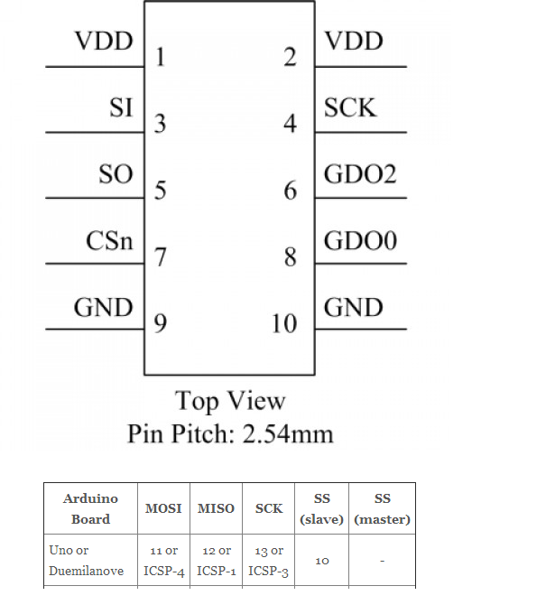
First lets start with the pins of the cc1101.

Here how it will connect to the arduino uno board (see here for other boards) :

To use the CC1101, you will need the panstamp library here.
Note that it will also work with the elechouse library here.
The initial thread on the Arduino forum.
Now lets have a look at the sketches.
Sending …
#include "EEPROM.h"
#include "cc1101.h"

CC1101 cc1101;

// The LED is wired to the Arduino Output 4 (physical panStamp pin 19)
#define LEDOUTPUT 7

// counter to get increment in each loop
byte counter;
byte b;
//byte syncWord = 199;
byte syncWord[2] = {199, 0};

void blinker(){
digitalWrite(LEDOUTPUT, HIGH);
delay(100);
digitalWrite(LEDOUTPUT, LOW);
delay(100);
}

void setup()
{
Serial.begin(38400);
Serial.println("start");

// setup the blinker output
pinMode(LEDOUTPUT, OUTPUT);
digitalWrite(LEDOUTPUT, LOW);

// blink once to signal the setup
blinker();

// reset the counter
counter=0;
Serial.println("initializing...");
// initialize the RF Chip
cc1101.init();

//cc1101.setSyncWord(&syncWord, false);
cc1101.setSyncWord(syncWord, false);
cc1101.setCarrierFreq(CFREQ_433);
cc1101.disableAddressCheck();
//cc1101.setTxPowerAmp(PA_LowPower);

delay(1000);

Serial.print("CC1101_PARTNUM "); //cc1101=0
Serial.println(cc1101.readReg(CC1101_PARTNUM, CC1101_STATUS_REGISTER));
Serial.print("CC1101_VERSION "); //cc1101=4
Serial.println(cc1101.readReg(CC1101_VERSION, CC1101_STATUS_REGISTER));
Serial.print("CC1101_MARCSTATE ");
Serial.println(cc1101.readReg(CC1101_MARCSTATE, CC1101_STATUS_REGISTER) & 0x1f);

Serial.println("device initialized");
//Serial.println("done");
}

void send_data() {
CCPACKET data;
data.length=10;
byte blinkCount=counter++;
data.data[0]=5;
data.data[1]=blinkCount;data.data[2]=0;
data.data[3]=1;data.data[4]=0;
//cc1101.flushTxFifo ();
Serial.print("CC1101_MARCSTATE ");
Serial.println(cc1101.readReg(CC1101_MARCSTATE, CC1101_STATUS_REGISTER) & 0x1f);
if(cc1101.sendData(data)){
Serial.print(blinkCount,HEX);
Serial.println(" sent ok :)");
blinker();
}else{
Serial.println("sent failed :(");
blinker();
blinker();
}
}

void loop()
{
send_data();
delay(4000);
}
Receiving …
#include "EEPROM.h"
#include "cc1101.h"

// The LED is wired to the Arduino Output 4 (physical panStamp pin 19)
#define LEDOUTPUT 4

// The connection to the hardware chip CC1101 the RF Chip
CC1101 cc1101;

byte b;
byte i;
byte syncWord = 199;
long counter=0;
byte chan=0;

// a flag that a wireless packet has been received
boolean packetAvailable = false;

void blinker(){
digitalWrite(LEDOUTPUT, HIGH);
delay(100);
digitalWrite(LEDOUTPUT, LOW);
delay(100);
}

/* Handle interrupt from CC1101 (INT0) gdo0 on pin2 */
void cc1101signalsInterrupt(void){
// set the flag that a package is available
packetAvailable = true;
}

void setup()
{
Serial.begin(38400);
Serial.println("start");

// setup the blinker output
pinMode(LEDOUTPUT, OUTPUT);
digitalWrite(LEDOUTPUT, LOW);

// blink once to signal the setup
blinker();
// initialize the RF Chip
cc1101.init();

cc1101.setSyncWord(&syncWord, false);
cc1101.setCarrierFreq(CFREQ_433);
cc1101.disableAddressCheck(); //if not specified, will only display "packet received"
//cc1101.setTxPowerAmp(PA_LowPower);

Serial.print("CC1101_PARTNUM "); //cc1101=0
Serial.println(cc1101.readReg(CC1101_PARTNUM, CC1101_STATUS_REGISTER));
Serial.print("CC1101_VERSION "); //cc1101=4
Serial.println(cc1101.readReg(CC1101_VERSION, CC1101_STATUS_REGISTER));
Serial.print("CC1101_MARCSTATE ");
Serial.println(cc1101.readReg(CC1101_MARCSTATE, CC1101_STATUS_REGISTER) & 0x1f);

attachInterrupt(0, cc1101signalsInterrupt, FALLING);

Serial.println("device initialized");
}

void ReadLQI()
{
byte lqi=0;
byte value=0;
lqi=(cc1101.readReg(CC1101_LQI, CC1101_STATUS_REGISTER));
value = 0x3F - (lqi & 0x3F);
Serial.print("CC1101_LQI ");
Serial.println(value);
}

void ReadRSSI()
{
byte rssi=0;
byte value=0;

rssi=(cc1101.readReg(CC1101_RSSI, CC1101_STATUS_REGISTER));

if (rssi >= 128)
{
value = 255 - rssi;
value /= 2;
value += 74;
}
else
{
value = rssi/2;
value += 74;
}
Serial.print("CC1101_RSSI ");
Serial.println(value);
}

void loop()
{
if(packetAvailable){
Serial.println("packet received");
// Disable wireless reception interrupt
detachInterrupt(0);

ReadRSSI();
ReadLQI();
// clear the flag
packetAvailable = false;

CCPACKET packet;

if(cc1101.receiveData(&packet) > 0){
if(!packet.crc_ok) {
Serial.println("crc not ok");
}

if(packet.length > 0){
Serial.print("packet: len ");
Serial.print(packet.length);
Serial.print(" data: ");
for(int j=0; j<packet.length; j++){
serial.print(packet.data[j],hex);
serial.print(" ");
}
serial.println(".");

 }
}
 // Enable wireless reception interrupt attachInterrupt(0, cc1101signalsInterrupt, FALLING);
}
}
Voila :)
You know should not a bit better on the cc1101 pins, on how to connect it to the arduino and you have basic code to developp your projects.