A video illustrating the previous article .
The red is a bit flashy, sorry for that…
Juil 062014
A video illustrating the previous article .
The red is a bit flashy, sorry for that…
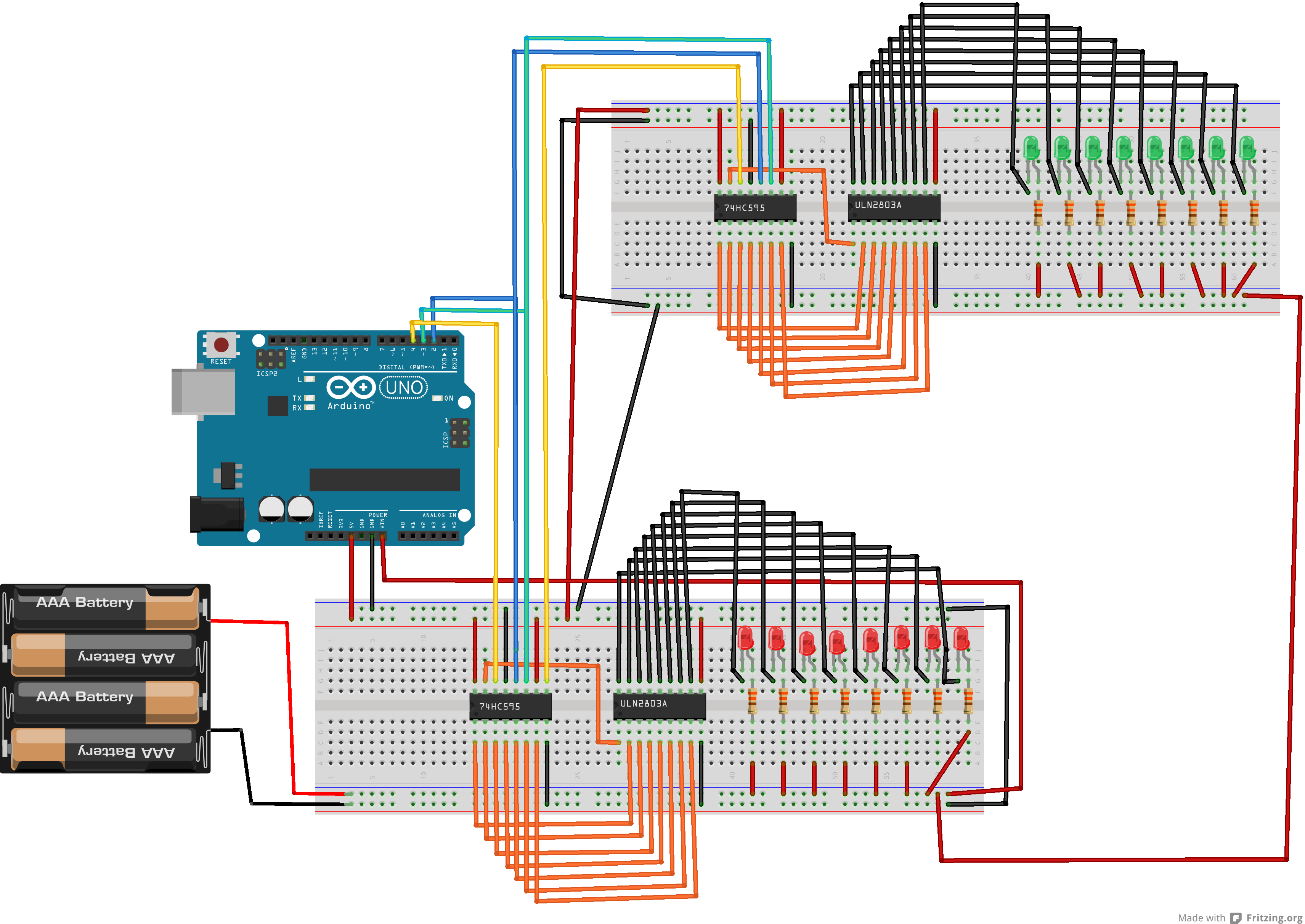
In a previous article, we had used a 74HC595 to control a ULN2803.
This enabled us to deal with 8 LED’s.
Lets now cascade two 74HC595 to deal with 16 LED’s.
To do this, we will use the serial output of 74HC595 #1 to the serial input of 74HC595 #2.
Here below the schema.
Here below the arduino sketch.
Note that we use two arrays, and that we go up and down in each array.
//the pins we are using
int latchPin = 2;
int clockPin = 3;
int dataPin = 4;


byte dataArrayA[9];
byte dataArrayB[9];

void setup() {
  //set all the pins used to talk to the chip
  //as output pins so we can write to them
  pinMode(latchPin, OUTPUT);
  pinMode(clockPin, OUTPUT);
  pinMode(dataPin, OUTPUT);

  dataArrayA[0] = 0xFF; //11111111
  dataArrayA[1] = 0xFE; //11111110
  dataArrayA[2] = 0xFC; //11111100
  dataArrayA[3] = 0xF8; //11111000
  dataArrayA[4] = 0xF0; //11110000
  dataArrayA[5] = 0xE0; //11100000
  dataArrayA[6] = 0xC0; //11000000
  dataArrayA[7] = 0x80; //10000000
  dataArrayA[8] = 0x00; //00000000

  dataArrayB[8] = 0xFF; //11111111
  dataArrayB[7] = 0xFE; //11111110
  dataArrayB[6] = 0xFC; //11111100
  dataArrayB[5] = 0xF8; //11111000
  dataArrayB[4] = 0xF0; //11110000
  dataArrayB[3] = 0xE0; //11100000
  dataArrayB[2] = 0xC0; //11000000
  dataArrayB[1] = 0x80; //10000000
  dataArrayB[0] = 0x00; //00000000

}

void loop() {
  for (int i = 0; i < 9; i++) {
    digitalWrite(latchPin, LOW);
    shiftOut(dataPin, clockPin, MSBFIRST, dataArrayA[i]);
    shiftOut(dataPin, clockPin, MSBFIRST, dataArrayB[i]);
    digitalWrite(latchPin, HIGH);
    delay(100);
  }

  for (int i = 8; i >= 0; i--) {
  digitalWrite(latchPin, LOW);
  shiftOut(dataPin, clockPin, MSBFIRST, dataArrayA[i]);
  shiftOut(dataPin, clockPin, MSBFIRST, dataArrayB[i]);
  digitalWrite(latchPin, HIGH);
  delay(100);
  }

}