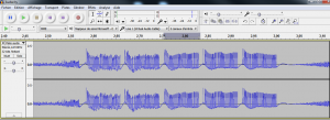
In previous article, we managed to decode a RF433 packet using homeeasy protocol (a di-o chacon telco for a power outlet).
Next obvious step is now to replay it using our Arduino and a FS1000a rf433 chip.
Here below the arduino sketch.
(wiring is simple : data to digital 3, gnd to gnd, vcc to 3.3v)
const int transmit_pin = 3;

void setup()
{
   pinMode(transmit_pin, OUTPUT);
    Serial.begin(115200);	// Debugging only
    Serial.println("setup");
}

void loop()
{
  //time to adjust
  digitalWrite(transmit_pin, LOW);
  delayMicroseconds(5000);
  //preamble
  digitalWrite(transmit_pin, HIGH);
  delayMicroseconds(275);
  digitalWrite(transmit_pin, LOW);
  delayMicroseconds(2800);
  //datas - a manchester encoded string, sniffed with sdrsharp
char binary[]={0,1,0,1,0,1,1,0,1,0,1,0,0,1,1,0,0,1,1,0,0,1,0,1,1,0,0,1,0,1,1,0,1,0,1,0,1,0,0,1,1,0,1,0,1,0,1,0,1,0,0,1,0,1,1,0,0,1,0,1,0,1,0,1};
for (int i=0; i <64; i++){
      if (binary[i]==0) {
        digitalWrite(transmit_pin, HIGH);
        delayMicroseconds(275);
        digitalWrite(transmit_pin, LOW);
        delayMicroseconds(275);
      }
      if (binary[i]==1) {
        digitalWrite(transmit_pin, HIGH);
        delayMicroseconds(275);
        digitalWrite(transmit_pin, LOW);
        delayMicroseconds(1225);
      }
   }
   //the end
   digitalWrite(transmit_pin, HIGH);
   delayMicroseconds(275);
   digitalWrite(transmit_pin, LOW);
  delayMicroseconds(5000);
  //
delay(1000);
  }
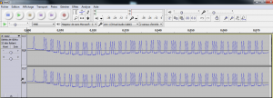
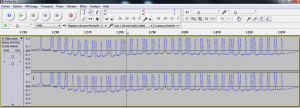
Here below the generated signal which as you can see is very similar to the original one.
The original


