Déc 022018
 

In previous article, we have seen how to flash an ESP8266 with ESPEasy.

Lets now see how easy it is to use a sensor such as a DHT11 temperature/humidity sensor.

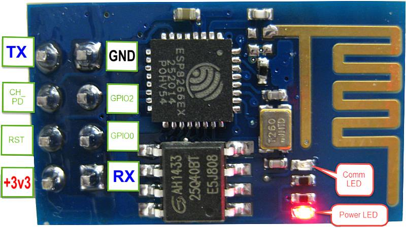
Lets wire 3v3 and ground and data to our esp8266 gpio 0.

Now, simply add a device on port GPIO 0 and pick a type « Environment – DHT11/12/22 ».

And your ESPEasy should now report temperature and humidity.

Déc 022018
 

I had this old esp-01 standing on my desk for a while and decided to dust it out by flashing Espeasy firmware.
About this esp8266, see previous articles here.

Note that if you are not sure which esp8266 you model you have, check it out here.

Before we flash, lets do some simple wiring :
-wire 3v3 and ground.
-wire tx to rx, and rx to tx (I use a usb to serial ftdi adapter)
-set gpio0 to low (ground)
-set ch_pd (also referred to en) to high (3v3)
-power off/on to enter flash mode

It is as simple as put your firmware next to flashesp8266.exe (in my case firmware is ESPEasy_mega-20180102_normal_ESP8266_1024.bin) and execute ESPEasy Flasher.

Once flash is completed, set gpio0 free (but leave ch_pd high), power off/on and you should see a new ssid on your network called esp_easy_0 (password=configesp).
configure it i.e connect it to your wireless network and you are done.

Déc 132015
 

Last ESP8266 example for the day (credit goes here) : a web server turning a lef off and on.


#include 
 
const char* ssid = "livebox0";
const char* password = "password";
 
int ledPin = 2; // GPIO2
WiFiServer server(80);
 
void setup() {
  Serial.begin(115200);
  delay(10);
 
  pinMode(ledPin, OUTPUT);
  digitalWrite(ledPin, LOW);
 
  // Connect to WiFi network
  Serial.println();
  Serial.println();
  Serial.print("Connecting to ");
  Serial.println(ssid);
 
  WiFi.begin(ssid, password);
 
  while (WiFi.status() != WL_CONNECTED) {
    delay(500);
    Serial.print(".");
  }
  Serial.println("");
  Serial.println("WiFi connected");
 
  // Start the server
  server.begin();
  Serial.println("Server started");
 
  // Print the IP address
  Serial.print("Use this URL to connect: ");
  Serial.print("http://");
  Serial.print(WiFi.localIP());
  Serial.println("/");
 
}
 
void loop() {
  // Check if a client has connected
  WiFiClient client = server.available();
  if (!client) {
    return;
  }
 
  // Wait until the client sends some data
  Serial.println("new client");
  while(!client.available()){
    delay(1);
  }
 
  // Read the first line of the request
  String request = client.readStringUntil('\r');
  Serial.println(request);
  client.flush();
 
  // Match the request
 
  int value = LOW;
  if (request.indexOf("/LED=ON") != -1)  {
    digitalWrite(ledPin, HIGH);
    value = HIGH;
  }
  if (request.indexOf("/LED=OFF") != -1)  {
    digitalWrite(ledPin, LOW);
    value = LOW;
  }
 
// Set ledPin according to the request
//digitalWrite(ledPin, value);
 
  // Return the response
  client.println("HTTP/1.1 200 OK");
  client.println("Content-Type: text/html");
  client.println(""); //  do not forget this one
  client.println("");
  client.println("");
 
  client.print("Led pin is now: ");
 
  if(value == HIGH) {
    client.print("On");
  } else {
    client.print("Off");
  }
  client.println("

"); client.println("Click here turn the LED on pin 2 ON
"); client.println("Click here turn the LED on pin 2 OFF
"); client.println(""); delay(1); Serial.println("Client disonnected"); Serial.println(""); }
Déc 132015
 

In previous article, we have seen how to talk to a 8266 thru serial.

We could do the same from an arduino and therefore use this module as a slave.
But why introduce a second MCU when the ESP8266 itself is a MCU?

Our arduino IDE can actually program such a MCU (next to the atmega series).
For this you will need latest arduino ide (version 1.6.4 and up).
You will also need to add support for the ESP8266 : see here how to do this.

Once done you are ready to program your MCU.
Dont forget to pull GPIO0 down but also to reset your MCU when entering the flash phase (or else you’ll get « error: espcomm_open failed »).
Once flashed, set GPIO0 free.

See below our arduino ide flashing the blink demo.

Déc 132015
 

In a previous article, we saw how I flashed my new ESP8266.

Now lets see how to « talk » with this module.

First wiring : chpd high, 3v3+gnd, tx to rx / rx to tx.

Lets launch putty,
select serial,
enter the right com port (com7 for me, using my usb to serial adapter),
select 9600 bauds (if it does not work, try 57600 or 115200).

Lets try the below command (ctrl/m + ctrl/j to enter):
-AT should respond OK
-AT+GMR should to get the firmware revision
-AT+CWMODE=3 to select AP & STA mode
-AT+CWLAP to list access points
-AT+CWJAP=“SSID”,“password” to connect to an AP
-AT+CIFSR to retrieve the ip (at this point you should be able to ping the module on your home wifi network)

Déc 122015
 

Just received my esp2866.
Read more about it here.
In short it is a wireless soc which you can control from a MCU (like Arduino) thru serial OR use directly as MCU (from Arduino IDE).

ESP8266

First things first : lets flash it with the latest firmware.

1-get the firmware here.
2-get the flasher here.
3-wire 3v3 and ground.
4-wire tx to rx, and rx to tx (I use a usb to serial ftdi adapter)
5-set gpio0 to low (ground)
6-reboot (power off/on will do)
7-flash
8-set gpio0 free
9-reboot and enjoy