Sep 262014
 

In previous article, thanks to a R820T tuner, we managed to capture some RF4333 signal (which seems to be repeated 5 times).

rf433_Audacity

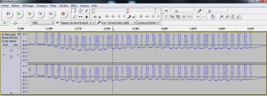
Zooming in one pattern, we can see high and low bits.

rf433_Audacity2

Googling around, it appears that my di-o chacon telco is using the homeeasy protocol.
a preamble (before data) is HIGH for 275us and a LOW for 2675us.
a 0 is HIGH for 275us and LOW for 275us.
a 1 is HIGH for 275us and LOW for 1225us.

We therefore end up with 64 bits (wired):
01 01 01 10 10 10 01 10 01 10 01 01 10 01 01 10 10 10 10 01 10 10 10 10 10 01 01 10 01 01 01 01.

Still reading the homeeasy protocol, we learn than 01=0 and 10=1 (manchester encoding).

The result is (32 bits, decoded) :
00011101010010011110111110010000

Bit 0 to 25 is the device id : 11101010010011110111110 -> 7527BE
Bit 26 is the flag group : 0
Bit 27 is on/off : 1
Bit 28 to 31 is the device code : 0000

Now re using this article, we should be able to replay that signal with the right timings.
Sep 212014
 

I got myself a cheap 4 digits 7-led display and I thought I would spend a few mns playing with it and documenting it.

4digits


12 pins : 8 for the segments (including the dots), 4 for each digit
Top row : 1, a, f, 2, 3, b
Bottomw row: e, d, dp, c, g, 4

I decided to use the Sevseg arduino library.
More about this library here.

The wiring is then as is :

Arduino pins -> 4digits display pins
2->1
6->a
11->f
3->2
4->3
7->b
10->e
9->d
13->dp
8->c
12->g
5->4

Below the schema

4digits_bb

Note that this is a lot of digital IO’s used. A future article could focus on reducing the number of IO’s needed.
Below the arduino sketch (from the example provided with the sevseg library)

/*Written by Dean Reading, 2012.  deanreading@hotmail.com
 
 This example is a centi-second counter to demonstrate the
 use of my SevSeg library.
 */

#include "SevSeg.h"

//Create an instance of the object.
SevSeg sevseg;

//Create global variables
unsigned long timer;
int CentSec=0;

void setup() {
  //I am using a common anode display, with the digit pins connected
  //from 2-5 and the segment pins connected from 6-13
  sevseg.Begin(1,2,3,4,5,6,7,8,9,10,11,12,13);
  //Set the desired brightness (0 to 100);
  sevseg.Brightness(50);

  timer=millis();
}

void loop() {
  //Produce an output on the display
  sevseg.PrintOutput();

  //Check if 10ms has elapsed
  unsigned long mils=millis();
  if (mils-timer>=10) {
    timer=mils;
    CentSec++;
    if (CentSec==10000) { // Reset to 0 after counting for 100 seconds.
      CentSec=0;
    }
    //Update the number to be displayed, with a decimal
    //place in the correct position.
    sevseg.NewNum(CentSec,(byte) 2);
  }
}
 Posted by at 18 h 08 min
Sep 192014
 

Finally received my DVB-T/DAB/FM dongle and more precisely my R820T tuner.

This, with the proper drivers (here), will allow me to « listen » to my RF433 radio devices.

sdrsharp

Even better I can record my signal in audacity using a « virtual audio cable« . (note that are free alternatives).

Or else I can display my packets using rtl_433_win32 (although not decoded properly).

rtl_433

Note : ab 53 32 cb 54 d5 4b 2a 80 is a chacon remote control (to switch on/off a 220v plug outlet).

We can see in audacity the pattern repeated 5 times.

rf433_Audacity

Zooming in one pattern, we can see high and low bits.

rf433_Audacity2

Now the challenge is the following :
-snif a RF433 packet and decode it
-replay it with my Arduino+CC1101

How fun 🙂

 Posted by at 20 h 00 min
Juil 072014
 

A small break away from coding and electronic…

I wanted to offer something special to my special geek girl so here it is : a jewel (earings) made of resistors 🙂

Two times 5 * 1.8Kohm : yes, I am not cheap, not counting !

IMG_4423

 Posted by at 21 h 42 min
Juil 062014
 

In a previous article, we had used a 74HC595 to control a ULN2803.
This enabled us to deal with 8 LED’s.

Lets now cascade two 74HC595 to deal with 16 LED’s.
To do this, we will use the serial output of 74HC595 #1 to the serial input of 74HC595 #2.

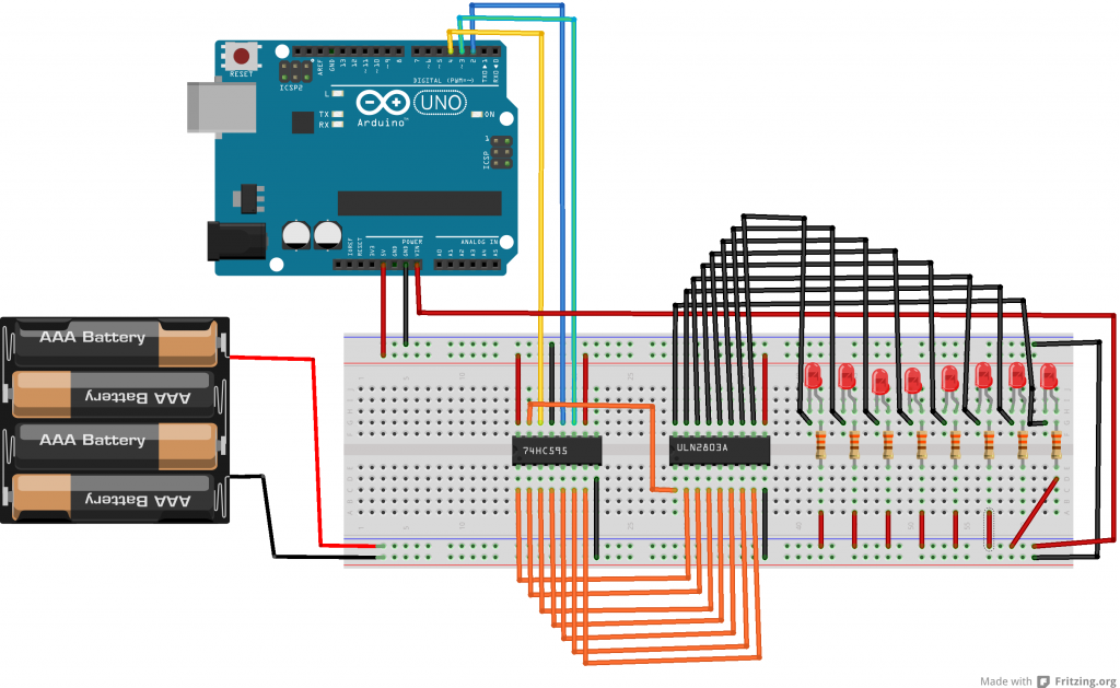
Here below the schema.

uln2803a_4_bb

Here below the arduino sketch.
Note that we use two arrays, and that we go up and down in each array.

//the pins we are using
int latchPin = 2;
int clockPin = 3;
int dataPin = 4;


byte dataArrayA[9];
byte dataArrayB[9];
 
void setup() {
  //set all the pins used to talk to the chip
  //as output pins so we can write to them
  pinMode(latchPin, OUTPUT);
  pinMode(clockPin, OUTPUT);
  pinMode(dataPin, OUTPUT);
  
  dataArrayA[0] = 0xFF; //11111111
  dataArrayA[1] = 0xFE; //11111110
  dataArrayA[2] = 0xFC; //11111100
  dataArrayA[3] = 0xF8; //11111000
  dataArrayA[4] = 0xF0; //11110000
  dataArrayA[5] = 0xE0; //11100000
  dataArrayA[6] = 0xC0; //11000000
  dataArrayA[7] = 0x80; //10000000
  dataArrayA[8] = 0x00; //00000000
  
  dataArrayB[8] = 0xFF; //11111111
  dataArrayB[7] = 0xFE; //11111110
  dataArrayB[6] = 0xFC; //11111100
  dataArrayB[5] = 0xF8; //11111000
  dataArrayB[4] = 0xF0; //11110000
  dataArrayB[3] = 0xE0; //11100000
  dataArrayB[2] = 0xC0; //11000000
  dataArrayB[1] = 0x80; //10000000
  dataArrayB[0] = 0x00; //00000000

}
 
void loop() {
  for (int i = 0; i < 9; i++) {
    digitalWrite(latchPin, LOW);
    shiftOut(dataPin, clockPin, MSBFIRST, dataArrayA[i]);  
    shiftOut(dataPin, clockPin, MSBFIRST, dataArrayB[i]);
    digitalWrite(latchPin, HIGH);
    delay(100);
  }

  for (int i = 8; i >= 0; i--) {
  digitalWrite(latchPin, LOW);
  shiftOut(dataPin, clockPin, MSBFIRST, dataArrayA[i]);
  shiftOut(dataPin, clockPin, MSBFIRST, dataArrayB[i]);  
  digitalWrite(latchPin, HIGH);
  delay(100);
  }
  
}
 Posted by at 19 h 39 min
Juin 082014
 

Here below a video illustrating the previous article.

On the proto board, you’ll notice a 74HC595 controlling a ULN2803 plugged to 8 leds.

I use the below array of byte to have the up and down effect

  dataArray[0] = 0xFF; //11111111
  dataArray[1] = 0xFE; //11111110
  dataArray[2] = 0xFC; //11111100
  dataArray[3] = 0xF8; //11111000
  dataArray[4] = 0xF0; //11110000
  dataArray[5] = 0xE0; //11100000
  dataArray[6] = 0xC0; //11000000
  dataArray[7] = 0x80; //10000000
  dataArray[8] = 0x00; //00000000

Juin 072014
 

Still on my journey to a wordclock…

In the previous article, we have seen how to use a shift register to control up to 8 digital outputs (or more if you cascade IC’s).

One drawback in the previous setup is that we had to use one transistor per digital output (to control a device powered by another source).
That is 8 extra transistors, 8*3 extra wires, etc : not very practical and especially if we intend to control several shift registers IC’s. (i plan on using 3 in my wordclock project)

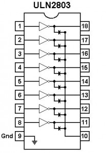
So this is where the ULN2803 comes in : 8 NPN transistors and one common ground in one integrated circuit.

uln2803

See below a refreshed schema (compared to the previous article). Note that I have decided to power my IC’s with my (regulated) Arduino 5v but I could as well have used my battery pack power.
Our 74HC595 will control our ULN2803 (by sending HIGH or LOW on the input) which in turn will drive the current thru each output/led.

uln2803a_bb

the Arduino sketch :

//the pins we are using
int latchPin = 2;
int clockPin = 3;
int dataPin = 4;
 
void setup() {
  //set all the pins used to talk to the chip
  //as output pins so we can write to them
  pinMode(latchPin, OUTPUT);
  pinMode(clockPin, OUTPUT);
  pinMode(dataPin, OUTPUT);
}
 
void loop() {
  for (int i = 0; i < 8; i++) {
 
    //take the latchPin low so the LEDs don't change while we are writing data
    digitalWrite(latchPin, LOW);
 
    //shift out the bits
    shiftOut(dataPin, clockPin, MSBFIRST, i);  
 
    //take the latch pin high so the pins reflect
    //the data we have sent
    digitalWrite(latchPin, HIGH);

    // pause before next value:
    delay(1000);
  }
}
Juin 052014
 

I have a wordclock project.

Before I get there, I need to learn about transistors (see previous article) to handle an external power source for my leds and a shift register to control lots of leds with an Arduino.

Why am I not using the digital pins?
For 2 reasons :
-the digital pins are there to input/output a logic (0/1), not power
-my arduino only has 14 digital pins (I need about 25 output)

So to sum it up, we will use
-an external power source to power on our leds,
-transistors to isolate the external power source from the arduino,
-a shift register (74HC595) to handle 8 outputs at once with only 3 pins.

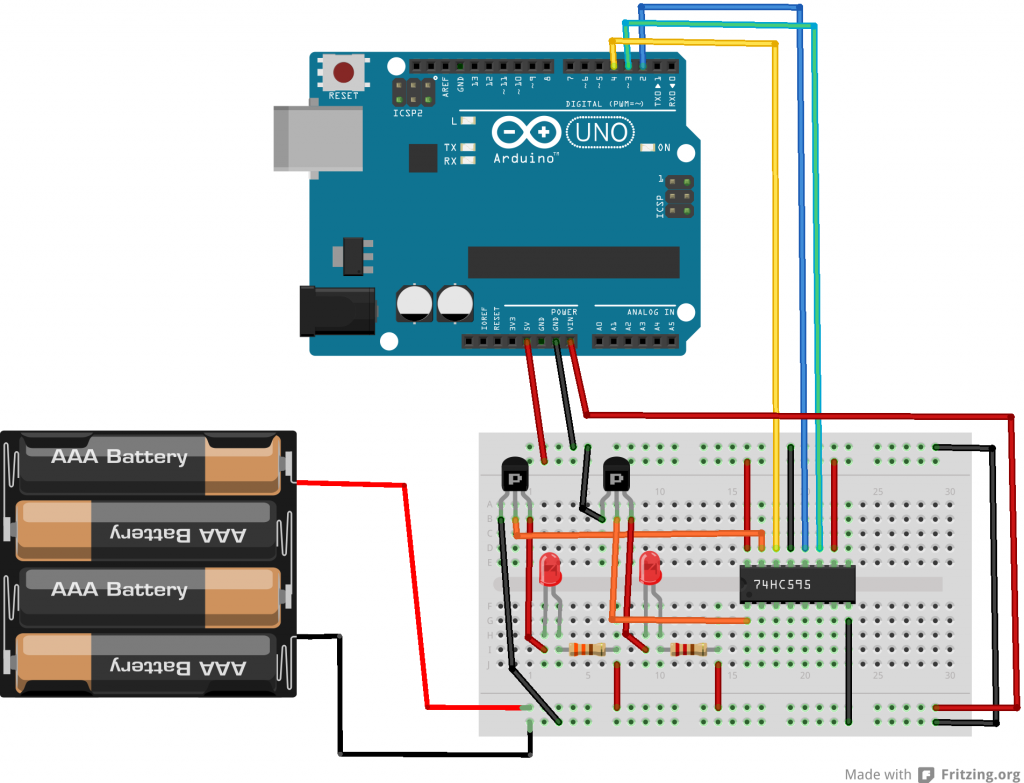
See below a wiring to use shift registers on two leds (it would be more impressive/significant with 8 leds with I was too lazy to draw it all).
Notice that we also use our external power source to power on the Arduino thru the vin pin.

About transistors, next evolution is to replace the serie of transistors by a transistor array like a uln2803a.

74HC595_3_bb


And now the arduino sketch.

note : all led on =b11111111 (255), 7 led on =b0111111, 6 led on=b00111111, etc …

//the pins we are using
int latchPin = 2;
int clockPin = 3;
int dataPin = 4;
 
void setup() {
  //set all the pins used to talk to the chip
  //as output pins so we can write to them
  pinMode(latchPin, OUTPUT);
  pinMode(clockPin, OUTPUT);
  pinMode(dataPin, OUTPUT);
}
 
void loop() {
  for (int i = 0; i < 8; i++) {
 
    //take the latchPin low so the LEDs don't change while we are writing data
    digitalWrite(latchPin, LOW);
 
    //shift out the bits
    shiftOut(dataPin, clockPin, MSBFIRST, i);  
 
    //take the latch pin high so the pins reflect
    //the data we have sent
    digitalWrite(latchPin, HIGH);

    // pause before next value:
    delay(1000);
  }
}
Juin 052014
 

A common mistake with Arduino beginners is to use the board to deliver power .
Altough it is ok for small devices such as sensors, leds, etc, it can only deliver 40ma (per pins) which wont work for more needy devices such as motors.

There comes the transistor which lets a small current control a much larger one and your Arduino can therefore manage devices which are power supplied from a separate source.
There are 2 sort of transistors : the PNP and the NPN.
The PNP will turn on with a LOW signal whereas the NPN will turn with a HIGH signal.

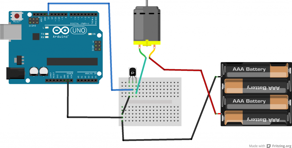
A transistor has 3 pins (looking at the labelled / flat side), from left to right : (C) the collector, (B) the base, (E) the emitter.
The collector is connected to the negative pin of the device. (the positive pin of the device being connected to the positive power supply)
The base is connected to the digital pin of the arduino.
The emitter is connected to the ground.

NPNvsPNP

See below the wiring

transistor2_bb

The the Arduino sketch is rather simple

int Pin = 9;

void setup(){
pinMode(Pin, OUTPUT);
}

void loop(){
digitalWrite(Pin, HIGH);
delay(2000);
digitalWrite(Pin, LOW);
delay(2000);

}
 Posted by at 13 h 34 min