Fév 212015
 

In previous article, my water pulse was settled in my garage.

Lets now design a wiring schema based on Arduino.
The idea is to use interrupts on the Arduino : it will be HIGH (i.e near 5V) always except and it will be LOW when the reed switch will be closed.
We then want to detect either when it is LOW, or FALLING, or CHANGE.
For now I’ll go for FALLING as this one is the easiest to implement.

rising-edgefalling-edge


We would then use something like the below :


//in the setup
attachInterrupt(1, CallBack, FALLING);

void CallBack(){
//the below check will software debounce our switch
if (millis()-last_water>500) {
last_water=millis();
water=water+1;
}
}

Next article will be about the code (a web server, logging to SD card, monitoring impulses …).

Fév 172015
 

For some years now I have monitoring and logging my energy consumption with an OWL 160.
Datas are then collected in a domotic box (a raspberry + jeedom)

Next step is now to do the same with water.
I have tried several solutions but came to the following conclusions :
-my counter needs to be located inside my house (as operating outside is not practical)
-i need to use a reliable solution like impulse

Therefore I bought the below product based on a reed switch : it will trigger an impulse for each liter.

Déc 242014
 

In a previous article, I have use an attiny85 + ds18b20 + rf433 to built a cheap temperature probe.

This time, I needed the humidity next to the temperature.
I then decided to use a dht11 (you can get it starting at 1.50€ on ebay).
Total cost is below 4€.

Here below the wiring.

tx_dht11_bb

Here rf433_sendOOK_at85_dht11 the arduino sketch (rename the txt file to ino).
You will also need this dht11 library.

Here some pictures. Notice that i used an old (but still good for my purpose) smartphone 3.7v battery.

IMG_4868

IMG_4865

IMG_4864

Nov 092014
 

I found a small microphone unused in some old box.
I decided I could play with it by plugging it to my arduino.
Was rather easy using the analogread function but it was lacking sensitivity.

Googling around it appeared I needed an op-amp. For less than 2 euros, I could get a 10 pieces batch on ebay.

See below the schematic.
Notice the voltage divider (r3 to 5v, r2 to gnd) to get a 2.5v voltage (5v / 2) : this way, you should read about 512 (1024 / 2) on the analog port when the microphone is off.
Notice the gain as well (r5/r4) which should give me about x75 gain (r5/r4*vin).

lm358_2

The Arduino sketch is rather simple : it will trigger a led when the reading goes about a certain value (that will depend on your mic and r0).

const int analogInPin = A0;  
const int ledPin=13;
int sensorValue = 0;        

void setup() {
  Serial.begin(38400); 
  pinMode(ledPin, OUTPUT); 
}

void loop() {
  digitalWrite(ledPin, LOW);
  sensorValue = analogRead(analogInPin);            
  if (sensorValue>640 || sensorValue<580) {
  Serial.print("sensor = " );                       
  Serial.println(sensorValue);   
  digitalWrite(ledPin, HIGH);  
  delay(50);
  }
  delay(50);                     
}
 Posted by at 16 h 56 min  Tagged with:
Oct 182014
 

In a previous article, we had use an Arduino + RF433 chip + DS28B20 to come up with a cheap temperature sensor.

We are going to improve the setup by replacing the Arduino Pro mini by an ATTINY85.
See here on how to flash an ATTINY85.

See rf433_sendOOK_at85 for the code.

Note that power consumption will be as low as 0.005ma (5ua) with a peak at 18ma when reading temp.

See below a revised wiring replacing the Arduino by an ATTINY85.

tx_ds18b20_v3_bb


 Posted by at 17 h 42 min
Oct 182014
 

In previous article, I made a cheap temperature probe using an arduino pro mini.

Still, the arduino pro mini is a bit overkill and i would like to keep it for prototyping my projects, not on « live » projects.

So lets have a look at the attiny85 :
-it is cheap (1€ a piece)
-runs at 8mhz
-has 8k programmable memory
-has very low power consumption

Sounds perfect for my needs !

Lets have a look at the pinout.

attiny45_85pinout

To flash this baby, I decided to use my arduino uno r3.
See below a quick how to.

1- unzip attiny under Documents\Arduino\hardware (you should end up with a folder attiny in there)
2- start the arduino ide and upload the arduinoisp sketch (in the arduino examples) to your « arduino uno r3 » board
3- choose « arduino as isp » under tools\programmer menu
4- choose « attiny85 (8mhz) » under tools\board
5- upload your sketch onto the attiny85

Lets see how to wire our attiny85 to your arduino.

flash_attiny85_bb

In a next article, we will see how to adapt this article for attiny85.

Hint : if you are getting the error « relocation truncated to fit », have a look here (and see to replace your ld.exe).

 Posted by at 13 h 46 min
Oct 062014
 

My little project this last week end.

I need to add a few rf433 oregon temperature sensors to be linked to my rfxcom + jeedom domotic box.
Unfortunately, these sensors (oregon THGR122N) are about 25€ (or 15€ using a cresta clone), not including shiping costs.

Therefore I decided to do a cheap one myself using :
-an arduino pro mini (2.50€)
-a fs1000a transmitter (1.50€)
-a ds18b20 (1€)

The whole thing uses less than 2ma when sleeping, and max 20ma when it reads temperature from the ds18b20.

Here comes the sketch rf433_sendOOK.
Note that that I am re using code from connectingstuff.net to send oregon 2.1 compatible packets.

Possible evolution would be to replace the arduino pro mini by an ATTINY85.

arduino_oregon

Here comes the wiring.

tx_ds18b20_v2_bb

 Posted by at 22 h 21 min
Sep 282014
 

In previous article, we managed to decode a RF433 packet using homeeasy protocol (a di-o chacon telco for a power outlet).

Next obvious step is now to replay it using our Arduino and a FS1000a rf433 chip.

Here below the arduino sketch.
(wiring is simple : data to digital 3, gnd to gnd, vcc to 3.3v)

const int transmit_pin = 3;

void setup()
{
   pinMode(transmit_pin, OUTPUT);
    Serial.begin(115200);	// Debugging only
    Serial.println("setup");
}

void loop()
{
  //time to adjust
  digitalWrite(transmit_pin, LOW);
  delayMicroseconds(5000);
  //preamble
  digitalWrite(transmit_pin, HIGH);
  delayMicroseconds(275);
  digitalWrite(transmit_pin, LOW);
  delayMicroseconds(2800);
  //datas - a manchester encoded string, sniffed with sdrsharp
char binary[]={0,1,0,1,0,1,1,0,1,0,1,0,0,1,1,0,0,1,1,0,0,1,0,1,1,0,0,1,0,1,1,0,1,0,1,0,1,0,0,1,1,0,1,0,1,0,1,0,1,0,0,1,0,1,1,0,0,1,0,1,0,1,0,1};
for (int i=0; i <64; i++){
      if (binary[i]==0) {
        digitalWrite(transmit_pin, HIGH);
        delayMicroseconds(275);
        digitalWrite(transmit_pin, LOW);
        delayMicroseconds(275);
      }
      if (binary[i]==1) {
        digitalWrite(transmit_pin, HIGH);
        delayMicroseconds(275);
        digitalWrite(transmit_pin, LOW);
        delayMicroseconds(1225);
      }
   } 
   //the end
   digitalWrite(transmit_pin, HIGH);
   delayMicroseconds(275);
   digitalWrite(transmit_pin, LOW);
  delayMicroseconds(5000);
  //
delay(1000);      
  }

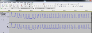
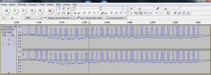
Here below the generated signal which as you can see is very similar to the original one.

rf433_arduino

The original

rf433_Audacity2

Sep 282014
 

Arduino : use a nokia 5110 lcd screen
Arduino : use a SD Card Reader
Arduino : a laser tag and a photo resistor
Arduino : play with a CC1101
Arduino : play with a potentiometer
Arduino : use a transistor
Arduino : use a shift register (74HC595)
Arduino : use a shift register (74HC595) and a transistor array (ULN2803)
Arduino : shift out leds
Arduino : Cascade two 74HC595
Arduino : Cascade two 74HC595 (video)
Arduino : 4 digits 7-led display

Previous recap #1

Arduino : display a clock based on a lcd screen and a RTC
Arduino : output to a tv (tvout)
Arduino : use a PS2 keyboard
Arduino : send and receive data thru radio frequency (RF433)
Arduino : programming an Arduino Pro Mini with an USB TTL Dongle
Arduino : use an ethernet controller (enc28j60)
Arduino : use it as an infrared remote
Arduino : use a Texas CC1101
Arduino : use your internal atmel 328p temperature

 Posted by at 13 h 24 min